Controlling Reactive Sputtering Processes: Why Voltage Control?
Veröffentlicht Januar 28, 2014 von Dave Christie
Reactive sputtering is used for a tremendous variety of industrial coating applications. In reactive sputtering processes, sputtered material is combined with reactive gas at the surface of the substrate to form a compound. Sometimes, the compound is insulating or dielectric, even though the magnetron target is conductive. There is, however, some complexity to controlling reactive sputtering processes. A simple model was created by Berg and his colleagues at Uppsala University [1]. This model helps to explain some of the phenomenology by tracking fluxes of ions, sputtered material, and process gas.
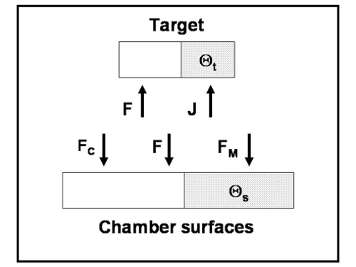
Reactive gas is consumed by the system pump, and is getter pumped at the chamber surfaces (including the objects being coated) and the target surface. The model equates the flow of gas into the chamber with the three consumption rates. Sputtered material travels from the target to the chamber surfaces. Both intrinsic target material and compound are assumed to be sputtered from the target surface, with uniform distribution to the chamber surfaces.
The figure below shows the fluxes of reactive gas, F, sputtered intrinsic target material, FM, sputtered compound, FC, and ions, J. The figure also shows that a fraction of the target surface, Øt, and a fraction of the chamber surfaces, Øs, are covered with compound. Getter pumping at the surfaces will occur only on the uncovered fractions. It is also important to note that the coverage fractions are not necessarily equal. The compound can have a much lower sputtering yield than the intrinsic target material, so when the target coverage fraction is high, the deposition rate can be low.
An example control curve for a reactive sputtering process is shown in the figure below. This is an illustrative example that shows some of the important characteristics of a reactive sputtering process from the control perspective. You can see that each value of voltage has a unique oxygen flow. On the other hand, some values of oxygen flow correspond to three values of voltage. Voltage can be used as a process control parameter, since there is a unique process working point for any given voltage on the curve.
Metallic mode, where target coverage fraction is very low, is at the top of the curve. Films deposited in metallic mode tend to have high absorption. Poisoned mode, where target coverage fraction is high, is at the bottom of the curve. Voltage is lower in poisoned mode since the secondary electron emission coefficient is higher for the dielectric covering most of the target, so less voltage is required to achieve the same (constant) process power. Films deposited in poisoned mode tend to have high optical quality; however, the deposition rate can be very low. The middle of the curve is the transition region, where both high optical quality (with low absorption) and high deposition rate are possible. Voltage control can be used to access this region.

Reference [1] S. Berg, et al., “Modeling of Reactive Sputtering of Compound Materials,” JVST A 5(2), Mar/Apr, p. 202, 1987.

Dave Christie
Verwandte Beiträge
Blog

.jpg?resizemode=force&maxsidesize=884)