Design Considerations for Maximum Temperature per IEC Safety Standards
Veröffentlicht Juli 27, 2021 von Alexander Mezin
Design Considerations for Maximum Allowable Temperature per Safety Standards IEC 60601-1, IEC 60950-1, IEC 62368-1, and IEC 61010-1
Safety standards dictate the requirements for products to remain safe during the normal operating condition of the product as well as during an abnormal single fault condition. Standards also require products to operate safely within a minimum set of environmental conditions, such as an ambient temperature range and supply voltage fluctuations. Temperature tests are performed at the specified temperature range, and at least the minimum range, specified in the relevant standard, to limit the risk of burn injuries or fires. Abnormal tests are performed to verify that the product will remain safe even when there is a fault condition, such as blocked cooling vents or a component short.
This article is intended as a guide and not a standard to review considerations in assessing potential hazards and risks posed by excessive temperatures and other hazards during normal use of the power supplies in equipment within the scope of the following standards:
- IEC 61010-1: Safety requirements for electrical equipment for measurement, control, and laboratory use Part 1: General requirements
- IEC 60950-1: Information technology equipment – Safety, Part 1: General requirements (replaced by IEC 62368-1 but still valid in some countries)
- IEC 60601-1: Medical electrical equipment, Part 1: General requirements for basic safety and essential performance
- IEC 62368-1: Audio/video, information, and communication technology equipment, Part 1: Safety requirements
Consult the appropriate regulatory standard(s) for your product to determine the actual requirements.
Enclosure Allowable Maximum Temperatures
A product enclosure or part that has excessive surface temperatures can injure or cause discomfort to a user. Additionally, if a component or material gets too hot it can cause burns to a person.
Information Technology Equipment safety IEC 60950-1, Test Equipment safety IEC 61010-1 and Audio/video, information and communication technology equipment IEC 62368-1 standards define maximum allowed temperature limits for operator access areas where the conditions of contact are divided into two main categories:
- Surfaces and parts are used to hold the equipment or control the functions. Listed examples of such parts are handles, knobs, grips, and similar. Touching these parts is necessary for normal equipment use.
- Every other internal or external surface of the equipment like enclosure, cables, or components may be touched accidentally.
The scope of Medical Safety standard IEC 60601-1 however is to provide safety requirements of equipment from an operator and patient contact perspective therefore the limits are categorized into:
- Medical electrical equipment, which includes those accessories that are necessary to enable the normal use of it.
- Applied part, which per definition is part of medical electrical equipment that in normal use necessarily comes into physical contact with the patient to perform its function.
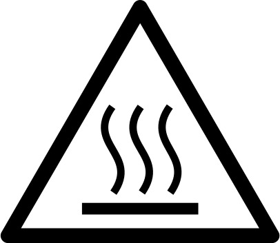
IEC 60950-1, IEC 62368-1 and IEC61010-1 standards provide rules if exceeding maximum allowed temperature is required for functionality. In such cases for example the equipment must be marked with standardized IEC 60417-5041 (2002-10) symbol.
Exceeding maximum allowed temperature per IEC 60601-1 must be documented in Risk Management File.
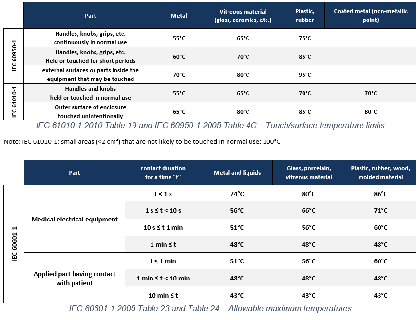
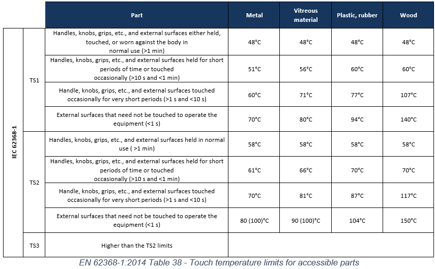
All four standards classify limits of the touchable surface temperature according to surface material and are listed in tables 23/24 of standard IEC 60601-1 3rd Ed., table 4C of standard IEC 60950-1 2nd Ed., table 38 of standard IEC 62368-1 2nd Ed. and table 19 of standard IEC 61010-1 as shown here as a guide. Check the actual standard for the current requirements.
While IEC 60601-1 specify maximum allowed temperature limits based on touch duration of the surface for each material for healthy skin of adults, IEC 60950-1 rate only short period touch vs. continuously held in normal use. In the standard IEC 61010-1: 2010 edition the surface temperature limits have been modified to conform to the limits of EN 563 which provide information about the effect of the duration of contact.

The IEC62368-1 standard extends the definition of short/long touch period with exact duration limits and also adds classification of three thermal energy categories TS1 –operation by an ordinary user, TS2 – operation by an informed user, TS3 – operation by a trained user.

Allowable Maximum Temperatures for embedded power supplies
Power supply mounting – Trade-offs
Proper layout in applications with internal power supplies consists of appropriate thermal design where generated heat by power components is checked and dissipated in the best available way. Generally, safety agency CB test reports of the mentioned standards list critical components with maximum rated temperature values which are to consider for enclosure construction. Derating curves in most datasheets show maximum power ratings versus ambient temperature of the power supply. These measurements are made in climate chambers on power supplies in unobstructed air conditions which may not be the actual case in the application. Integration of power supply unit into the system creates heat barriers hence the temperature of the components may rise. For example, enclosing the power supply with covers or mounting it close to walls or other elements creates heat traps in the system and so decreases the heat dissipation efficiency of the unit.
Contact your local field applications team to help to identify components of the power supply with maximum rated temperatures.
Identifying temperature critical components – example
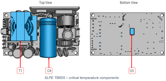
A power supply from SL Power Electronics TB65S Family can be taken as an example while determining heat critical components. The 3D picture shows three components with critical temperatures that were identified based on the safety CB test report and must be monitored:
.png)
- Bulk capacitor C4 is an electrolytic capacitor and is significantly affected by temperature. AC ripple currents in these capacitors create additional heat. The higher the long-term temperature of the electrolytic capacitors, the shorter the life of the component. In particular, in this example, it is strongly recommended to keep the capacitor’s temperature 5 – 10 ° C below the max allowed value of 105°C under worst-case conditions, especially without active airflow.
- Main Transformer Winding T1 is the main power element allowing maximum temperature up to 130 °C in this design. While selecting other system elements near this transformer designer should keep in mind the high temperature that these closely mounted system elements must withstand.
- Located on the bottom of the printed circuit board Opto-Coupler Body U3 is rated to a maximum of 115 °C therefore needs to have enough spacing between the power supply unit and system enclosure. Mounting TB65S on >5 mm standoffs ensures proper heat dissipation.
Temperature test requirements – measurement guideline
Information technology equipment – IEC 60950-1 (replaced Dec. 2020 by IEC 62368-1)
Maximum operating temperatures apply to components/materials including those that carry, support, or contain hazardous voltage or current. As an example, a plastic enclosure has two temperature ratings, maximum surface temperature, and its own maximum operating ambient air temperature. Used materials shall be selected so that under normal load, the temperature limits will not be exceeded.
The designer should consider effective shielding of components working at higher temperatures to avoid overheating of other systems parts in the application. Helpful information sources besides thermal measurements are material datasheets.
The unit under temperature test should be operated under normal load conditions in accordance to supply voltage concerning worst-case condition until the temperature has stabilized. Common power supplies support a wide input voltage range to cover worldwide AC mains networks. The standard defines the supply voltage tolerance to be +6 % and –10 % unless wider tolerance is declared by the supplier.
Both the IEC 60950-1 and IEC 62368-1 standards permit to test components or parts as a standalone unit as long as the test conditions are similar to those in the complete systems where the unit under test should be installed into.
Medical equipment IEC 60601-1
IEC 60601-1 Safety standard defines additional setup conditions to test medical electrical equipment hence power supply.
Positioning:
The ME Power Supply Adapter is placed in a test corner which consists of two walls with right angles, a floor and, if necessary, a ceiling, all of the dull black painted plywood of 20 mm thickness. The linear dimensions of the test corner are at least 115% of the linear dimensions of the ME Power Supply Adapter under test. The ME Power Supply Adapter is positioned in the test corner as follows:
- ME Power Supply Adapter normally used on a floor or a table is placed as near to the walls as is likely to occur in normal use.
- ME Power Supply Adapter normally affixed to a wall is mounted on one of the walls, as near to the other wall and to the floor or ceiling as is likely to occur in normal use.
- ME Power Supply Adapter normally affixed to a ceiling is mounted on the ceiling as near to the walls as is likely to occur in normal use.
Thermal Stabilization:
- ME Power Supply Adapter intended for non-continuous operation: After operating in standby/quiescent mode until thermal stability is reached, the ME Power Supply Adapter is operated in normal use over consecutive cycles until thermal stability is again achieved, or for 7 hours , whichever is shorter. The “on” and “off” periods for each cycle are the rated “on” and “off” periods
- ME Power Supply Adapter for continuous operation: The Power Supply Adapter is operated until thermal stability is reached
Equipment for measurement, control, and laboratory use IEC 61010-1
The temperature tests are made similar to general safety requirements as per IEC 60950-1 in normal condition use. IEC 61010-1 standard allows determining the maximum temperature levels by measuring the temperature rise under reference test conditions and adding this rise to 40°C or the maximum rated ambient temperature if higher.
For equipment intended to produce heat for functional purposes, IEC 61010-1 also requires correct positioning in the test corner, a power supply considered here as a part of the equipment, and obviously built-in internally. Applying this test to external power supplies should be justified:
The equipment with power supply is placed in a test corner which consists of two walls right angles, a floor and, if necessary, a ceiling, all of the dull black painted plywood of 20 mm thickness. The linear dimensions of the test corner are at least 115 % of the linear dimensions of the equipment under test. Equipment is positioned at the distances from the walls, ceiling, or floor specified by the manufacturer. If no distances are specified then:
- Equipment with a power supply normally used on a floor or a table is placed as near to the walls as is likely to occur in normal use.
- Equipment with a power supply normally affixed to a wall is mounted on one of the walls, as near to the other wall and to the floor or ceiling as is likely to occur in normal use.
- Equipment with a power supply normally affixed to a ceiling is mounted on the ceiling as near to the walls as is likely to occur in normal use.
If equipment is intended for installation in a cabinet or a wall it is built in as specified in the installation instructions, using walls of plywood painted matt black, approximately 10 mm thick when representing the walls of a cabinet, approximately 20 mm thick when representing the walls of a building.
Thermal Test Setup
1. As a rule of thumb for best worst-case thermal verification, use the lowest-rated line input voltage with the highest rated load. Place thermocouples on the listed components on a non-conductive area to measure excessive temperatures and to determine the correct thermal design.
2. Analyze accessible enclosure surfaces and critical components to identify the hottest locations on touchable surfaces and critical components/materials, including internal components and materials.
3. Attach thermocouples (TCs) for measurements:
- Affix TCs to several locations on the enclosure for surface measurements, such as on the hottest metal and plastic surfaces including enclosure top, sides, bottom, and air openings.
- Affix TCs to the hottest plastic materials and internal components, and where temperature rise could exceed the materials/components maximum operating temperature.
4. Perform the temperature test:
- Make and record measurements at +10% and -10% of the product’s voltage rating.
- Temperature chambers may be used, especially when the temperature rating of the product exceeds 40 °C. Cooling due to chamber air circulation should be minimized. Otherwise, this can significantly influence the results.
- Monitor and record temperature until they stabilize for a minimum of an hour (thermal stabilization for medical equipment explained above)
5. The stabilized temperature result measurements of the touch surfaces must not exceed the temperature limits in tables as specified in the corresponding standard.
Caution! In internal power supplies, the components with critical temperature are often located on the primary side of the AC-DC power supply! Use appropriate safety measures as these components are at hazardous voltage levels. Only qualified personnel should attempt to make these measurements.
