Controlling Pulsed DMS Reactive Sputtering Processes: Getting a Solid Voltage Feedback Signal
Posted April 22, 2014 by Dave Christie
Large-area coating is used to deposit complex layer systems on glass for architectural and automotive applications, and a myriad of others, including coatings on flexible webs. Some of the layers are compounds, which may be dielectrics, or transparent conductive oxides (TCOs). These layers are commonly deposited by reactive sputtering. Dual magnetron sputtering (DMS) is now the typical choice for reactive deposition in large-area coaters.
In the reactive DMS process, material is sputtered from the surface of the target, and travels to the surface of the glass. The reactive gas combines with the target material at the glass surface to form the compound. The difficulty comes from another surface reaction. The reactive gas also reacts with the surface of the target (It is in fact sub-planted into the target surface.), forming a compound at and slightly below the surface. When a small fraction of the target is covered with compound, it is said to be in the metallic mode. When a large fraction of the target is covered with compound, it is said to be in the poisoned mode. The compound typically has a lower sputtering yield than the target material, so deposition rate is reduced. In some cases, the sputtering yield for the compound is only 10% of the sputtering yield for the pure target material. There is an intermediate operating point, called the transition mode. It is between the metallic and poisoned modes. In the transition mode, it is possible to deposit films with high optical quality at high deposition rates. A feedback control system is required to maintain operation in the transition mode, with voltage, reactive gas partial pressure, or optical emission used for feedback.
When a reactive process is operated at constant power, it has a unique control curve with respect to oxygen and voltage, as shown in the figure below. This is an illustrative example created to explain key concepts. There is a unique value of oxygen flow for each voltage. On the other hand, there can be multiple values of voltage for some oxygen flows; there is a region where there are three possible voltages for a particular oxygen flow value. Consequently, voltage could be useful as feedback for closed-loop control, but flow would not. The top part of the curve corresponds to the metallic mode, where the film has high deposition rate. The films deposited in this region have a high metal content, with high optical absorption, and are generally not suitable as dielectric layers. The middle part is the transition region, where the deposition rate is high. Films produced here can have low optical absorption and can be quite useful as dielectric layers. The bottom part of the curve corresponds to the poisoned mode, where deposition rate is low, the process is intrinsically stable, and films produced have low optical absorption with good optical quality for use as dielectric layers.
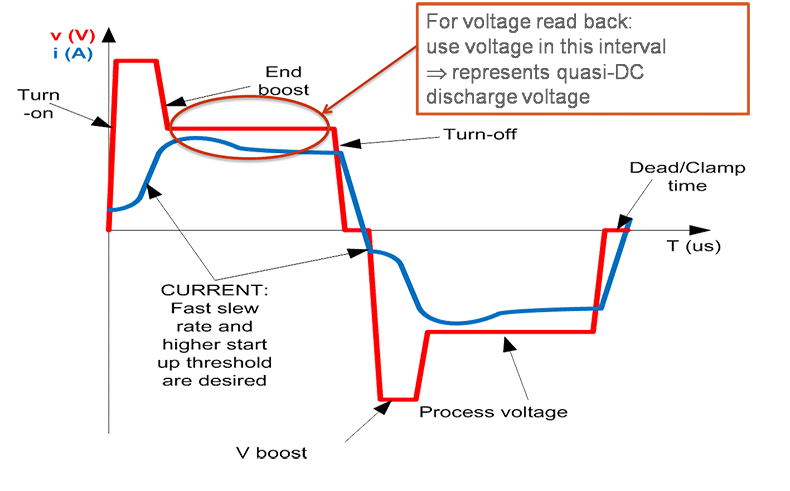
A waveform specifically designed for driving pulsed DMS systems is shown in the figure below. Quasi-DC sputtering conditions exist in the flat portion of the waveform, after switching transients are passed. This is where voltage measurements representing the quasi-DC sputtering voltage are taken, providing a good indication of the fraction of the target surface covered with compound and the relative target consumption rates. A voltage measurement here provides a solid signal for controlling the reactive sputtering process in the transition region. The AE DMS Accessory provides this type of voltage feedback for use in controlling reactive sputtering processes.


Dave Christie
Related Posts
Blog

.jpg?resizemode=force&maxsidesize=884)