The Story of 4-Wire Measurement
投稿 2月 25, 2021 によって Advanced Energy Editor
It is common knowledge in industry that 4-wire measurement is the preferred method for resistances under 1 Ω, but what makes it so advantageous over 2- and 3- wire measurement? Let’s look at how the technique was invented and why it works.


If this formula looks familiar, it is because it is simply Ohm’s Law.
Thanks to the ingenious method Kelvin devised over a century and a half ago, the resistance of 4-wire instrument leads will not affect the reading. While components have become smaller and faster, the idea remains the same.
For more information about 4-wire applications, check out our Application Note on Resistance Measurements of Small-Scale Components Using the TEGAM Model 1740 Micro-ohmmeter.
You may also be interested in TEGAM’s new 710A bond meter/milli-ohmmeter. Please contact us with any questions you may have before purchasing our test & measuring instruments.
Building Bridges
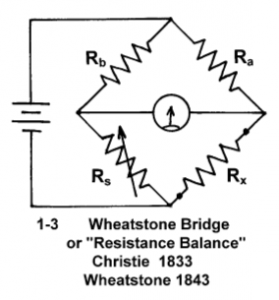
William Tomson, later Lord Kelvin of temperature scale fame, was studying Wheatstone bridge errors in the mid-1800s (See Figure 1). His concern was that the ratio arms (Ra, Rb) of the bridges contributed more to measurement error as the value of the measured resistance became lower (Rx).
Figure 1: Wheatstone Bridge
His solution to this problem became known as the Kelvin Double Bridge (See Figure 2). By integrating a second pair of ratio arms (Ra’ and Rb’) he divided the voltage drop proportionately so that Rx/Rs = Ra/Rb = Ra’/Rb’.
Figure 2: Kelvin Double Bridge
Now that the bridge is mathematically balanced, the resistance of all arms of the bridge have been canceled out. This is the basic principle behind 4-wire measurement, or Kelvin sensing, used in equipment from handheld devices to laboratory grade Ohmmeters.Ohm Sweet Ohm
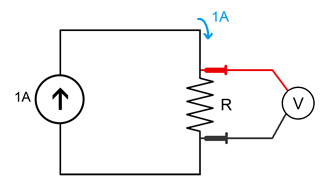
In Kelvin sensing, a known current source is applied to the component being measured and the voltage drop is measured at the lead tips, negating any lead resistance present. All four measurement nodes are brought to the front of the instrument by the way of Kelvin clips or probes.
Figure 3: Schematic Representation of Kelvin Sensing
The Drive side of the probe is the current source, and the Sense side of the probe is where the voltage drop is measured. The V+ (Sense) and I+ (Drive) are paired in one probe and the V- (Sense) and I- (Drive) are paired in the other. When the probes are placed on either side of a component, an electric circuit is completed, and the resistance can be calculated as follows:
If this formula looks familiar, it is because it is simply Ohm’s Law.
Thanks to the ingenious method Kelvin devised over a century and a half ago, the resistance of 4-wire instrument leads will not affect the reading. While components have become smaller and faster, the idea remains the same.
For More Information
Advanced Energy's TEGAM has sold specialty ohmmeters since the early 1990s, One of TEGAM’s areas of engineering and manufacturing expertise is within our lines of bond meters and bond meter probes for various industries and applications. From our intrinsically safe (ATEX, UL & CSA) bond meters to our full line of milli-ohmmeters, you can trust TEGAM when your measurements really matter.For more information about 4-wire applications, check out our Application Note on Resistance Measurements of Small-Scale Components Using the TEGAM Model 1740 Micro-ohmmeter.
You may also be interested in TEGAM’s new 710A bond meter/milli-ohmmeter. Please contact us with any questions you may have before purchasing our test & measuring instruments.
Advanced Energy Editor
Advanced Energy
